- 您现在的位置:买卖IC网 > Sheet目录333 > IRS26302DJTRPBF (International Rectifier)IC GATE DRIVER 3PH BRIDGE 44PLCC
�� �
�
�IRS26302DJ�
�The� length� of� the� fault� clear� time� period� can� be� determined� by� using� the� formula� below.�
�v� C� (t)� =� V� f� (1-e�
�-t/RC�
�)�
�t� FLTCLR� =� -(R� RCIN� C� RCIN� )ln(1-V� RCIN,TH� /V� CC� )�
�Over-Current� Protections�
�The� IRS26302DJ� HVICs� are� equipped� with� an� ITRIP,� GF� and� PFCtrip� input� pin.� These� functionality� can� be� used� to�
�detect� over-current� events� in� the� DC-� bus,� in� the� DC+� bus,� in� the� PFC� section� and� Ground� related.� Once� the� HVIC�
�detects� an� over-current� event,� the� outputs� are� shutdown,� a� fault� is� reported� through� the� FAULT� pin,� and� RCIN� is�
�pulled� to� V� SS� .�
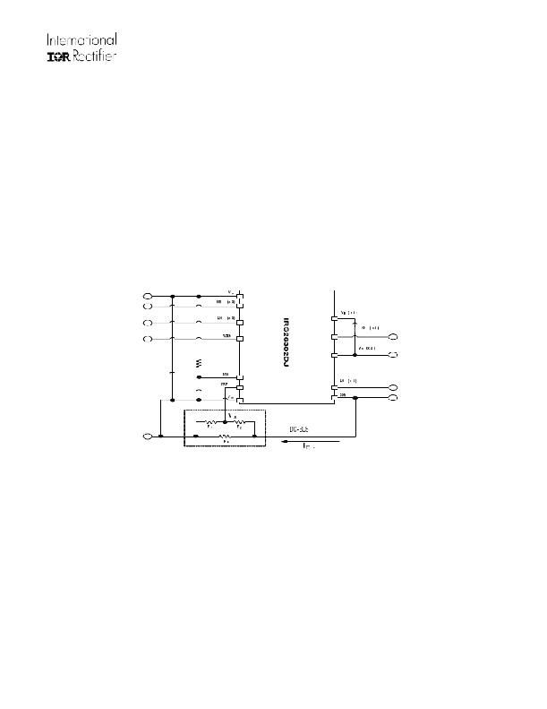
�The� level� of� current� at� which� the� over-current� protection� is� initiated� is� determined� by� the� resistor� network� (i.e.,� R� 0� ,� R� 1� ,�
�and� R� 2� )� connected� to� ITRIP� as� shown� in� Figure� 14,� and� the� ITRIP� threshold� (V� IT,TH+� ).� The� circuit� designer� will� need� to�
�determine� the� maximum� allowable� level� of� current� in� the� DC-� bus� and� select� R� 0� ,� R� 1� ,� and� R� 2� such� that� the� voltage� at�
�node� V� X� reaches� the� over-current� threshold� (V� IT,TH+� )� at� that� current� level.�
�V� IT,TH+� =� R� 0� I� DC-� (R� 1� /(R� 1� +R� 2� ))�
�Figure� 14:� Programming� the� over-current� protection�
�For� example,� a� typical� value� for� resistor� R� 0� could� be� 50� m� .� The� voltage� of� the� ITRIP� pin� should� not� be� allowed� to�
�exceed� 5� V;� if� necessary,� an� external� voltage� clamp� may� be� used.�
�The� shunt� resistor� or� resistor� network� for� GF� or� PCFtrip� can� be� determined� according� to� GF,� PCFtrip� threshold� and�
�level� of� protection� current.� The� GF� pin� should� not� be� outside� this� range� (VDC+0.3V,� VDC-5V)� and� PCFtrip� should� not�
�be� outside� (Vcc+0.3V,� Vss-5V);� if� necessary,� an� external� voltage� clamp� may� be� used.�
�Over-Temperature� Shutdown� Protection�
�The� ITRIP� input� of� the� IRS26302DJ� can� also� be� used� to� detect� over-temperature� events� in� the� system� and� initiate� a�
�shutdown� of� the� HVIC� (and� power� switches)� at� that� time.� In� order� to� use� this� functionality,� the� circuit� designer� will�
�need� to� design� the� resistor� network� as� shown� in� Figure� 15� and� select� the� maximum� allowable� temperature.�
�This� network� consists� of� a� thermistor� and� two� standard� resistors� R� 3� and� R� 4� .� As� the� temperature� changes,� the�
�resistance� of� the� thermistor� will� change;� this� will� result� in� a� change� of� voltage� at� node� V� X� .� The� resistor� values� should�
�www.irf.com�
�23�
�?� 2009� International� Rectifier�
�发布紧急采购,3分钟左右您将得到回复。
相关PDF资料
IRS26310DJTRPBF
IC DRIVER MOSFET/IGBT 44-PLCC
IRS4427PBF
IC MOSFET DRIVER
IRS4427SPBF
IC DVR LOW SIDE DUAL 8-SOIC
IRS4428STRPBF
IC DVR LOW SIDE DUAL 8-SOIC
ISL2100AAR3Z
IC DVR HALF-BRDG HF 100V 2A 9DFN
ISL2111ABZ
IC MSFT DVR HALF-BRG 100V 8-SOIC
ISL6160EVAL2
EVAL BOARD FOR ISL6160/HIP6006
ISL6207CBZ
IC DRIVER MOSFET DUAL SYNC 8SOIC
相关代理商/技术参数
IRS26310DJPBF
功能描述:功率驱动器IC 3-Phase DC BUS 600V 200mA 530ns RoHS:否 制造商:Micrel 产品:MOSFET Gate Drivers 类型:Low Cost High or Low Side MOSFET Driver 上升时间: 下降时间: 电源电压-最大:30 V 电源电压-最小:2.75 V 电源电流: 最大功率耗散: 最大工作温度:+ 85 C 安装风格:SMD/SMT 封装 / 箱体:SOIC-8 封装:Tube
IRS26310DJTRPBF
功能描述:功率驱动器IC Pwr MOSFT & IGBT Drvr HiVolt Hi Spd RoHS:否 制造商:Micrel 产品:MOSFET Gate Drivers 类型:Low Cost High or Low Side MOSFET Driver 上升时间: 下降时间: 电源电压-最大:30 V 电源电压-最小:2.75 V 电源电流: 最大功率耗散: 最大工作温度:+ 85 C 安装风格:SMD/SMT 封装 / 箱体:SOIC-8 封装:Tube
IRS27951
制造商:未知厂家 制造商全称:未知厂家 功能描述:
IRS27951S
制造商:IRF 制造商全称:International Rectifier 功能描述:Programmable minimum and maximum switching frequency
IRS27951SPBF
功能描述:功率驱动器IC 600V HALF BRDG HI VTG CTRLLER IC RoHS:否 制造商:Micrel 产品:MOSFET Gate Drivers 类型:Low Cost High or Low Side MOSFET Driver 上升时间: 下降时间: 电源电压-最大:30 V 电源电压-最小:2.75 V 电源电流: 最大功率耗散: 最大工作温度:+ 85 C 安装风格:SMD/SMT 封装 / 箱体:SOIC-8 封装:Tube
IRS27951STRPBF
功能描述:功率驱动器IC Resonant 1/2 Brdg Cntrl IC RoHS:否 制造商:Micrel 产品:MOSFET Gate Drivers 类型:Low Cost High or Low Side MOSFET Driver 上升时间: 下降时间: 电源电压-最大:30 V 电源电压-最小:2.75 V 电源电流: 最大功率耗散: 最大工作温度:+ 85 C 安装风格:SMD/SMT 封装 / 箱体:SOIC-8 封装:Tube
IRS27952
制造商:IRF 制造商全称:International Rectifier 功能描述:Programmable minimum and maximum switching frequency
IRS279524
制造商:IRF 制造商全称:International Rectifier 功能描述:Programmable minimum and maximum switching frequency